Monday, June 25, 2007

Rigid Body Dynamics, part 2

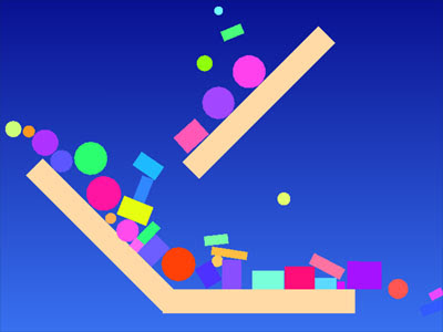
My rigid-body dynamics program now handles discs in addition to boxes. Since there is still no friction, there is no way yet to affect a disc's spin.


Boxes and discs share much in common: they have mass, rotational inertia, momentum, position, orientation, color, and elasticity. They differ only in their geometry, which affects how they are drawn and how they collide.

I created a simple class hierarchy to represent boxes and discs. Both of them derive from a class called Body which contains all of the common state. The Box class adds width and height, while the Disc class has a radius instead. Here is how the classes stand now:

class Box;
class Disc;

class Body
{
public:

virtual void draw() const = 0;

virtual void integrate(float dt);

virtual void compute_contacts(Body &, Contacts &) = 0;
virtual void compute_contacts(Box &, Contacts &) = 0;
virtual void compute_contacts(Disc &, Contacts &) = 0;

vec2 pt_velocity(vec2 p) const;

vec2 pos; // position
vec2 vel; // linear velocity
float angle; // heading
float angle_vel; // angular velocity
float inv_mass; // inverse mass
float inv_rot; // inverse of rotational inertia tensor
float life; // remaining lifetime, in seconds
float bounciness; // 0 to 1
vec3 color;
};

class Box : public Body
{
public:
virtual void draw() const;

virtual void integrate(float dt);

virtual void compute_contacts(Body &, Contacts &);
virtual void compute_contacts(Box &, Contacts &);
virtual void compute_contacts(Disc &, Contacts &);

vec2 radius; // half width, height in local space
vec2 x_axis; // computed, cached axes
vec2 y_axis;
};

class Disc : public Body
{
public:
virtual void draw() const;

virtual void compute_contacts(Body &, Contacts &);
virtual void compute_contacts(Box &, Contacts &);
virtual void compute_contacts(Disc &, Contacts &);

float radius;
};


The draw method is overridden by Box and Disc to draw the appropriate geometry. integrate is implemented at the Body level since it is the same for both kinds of bodies. The Box version call's Body's, then recalculates its axes based on the new box orientation. (The axes are used a bunch during contact determination, so it's good to have them computed only once per frame.)

The first step of collision handling is to collect a list of contacts between pairs of objects. (Last week, I handled each collision as I found it, but I'm trying to move toward the creation of forces to handle resting contact, so I need the whole set of contacts at once.)

To compute contacts, the program has to consider pairs of objects and decide:
  • If they are touching
  • Where they are touching
  • What the surface normal is at the contact
  • How deeply they are interpenetrating
As in the tutorials, I have a Contact structure that contains this information:

struct Contact
{
Body * a;
Body * b;
vec2 pos; // world-space contact position
vec2 normal; // world-space contact normal (points away from body a)
float depth; // interpenetration distance (positive when interpenetrating)
};


The central loop that compares each pair of bodies does not know whether a particular body is a box or a disc. I use a two-stage virtual method dispatch to resolve the types of the two bodies. Here's the top-level loop (at the moment I am not doing any culling by bounding-box or otherwise, so all pairs are considered):

static void find_contacts(const Bodies & bodies, Contacts & contacts)
{
contacts.clear();

Bodies::const_iterator body_end = bodies.end();
Bodies::const_iterator body1 = bodies.begin();
for (; body1 != body_end; ++body1)
{
Bodies::const_iterator body2 = body1;
for (++body2; body2 != body_end; ++body2)
{
if ((*body1)->inv_mass == 0 && (*body1)->inv_rot == 0 &&
(*body2)->inv_mass == 0 && (*body2)->inv_rot == 0)
continue;

(*body1)->compute_contacts(**body2, contacts);
}
}
}


This method is overridden for boxes and discs, so the type of body1 is established. These methods then call the appropriate methods on body2, passing the first object as an argument (but with known type now). Here's the code:

void Box::compute_contacts(Body & body, Contacts & contacts)
{
body.compute_contacts(*this, contacts);
}

void Box::compute_contacts(Box & box, Contacts & contacts)
{
box_box_contacts(*this, box, contacts);
}

void Box::compute_contacts(Disc & disc, Contacts & contacts)
{
disc_box_contacts(disc, *this, contacts);
}

void Disc::compute_contacts(Body & body, Contacts & contacts)
{
body.compute_contacts(*this, contacts);
}

void Disc::compute_contacts(Box & box, Contacts & contacts)
{
disc_box_contacts(*this, box, contacts);
}

void Disc::compute_contacts(Disc & disc, Contacts & contacts)
{
disc_disc_contacts(*this, disc, contacts);
}


Once both body types are known, the correct function for computing contacts can be called. It's one of these three:

void box_box_contacts(Box & box1, Box & box2, Contacts &);
void disc_box_contacts(Disc & disc, Box & box, Contacts &);
void disc_disc_contacts(Disc & disc1, Disc & disc2, Contacts &);


As you can see, this is sort of a hack to get the functionality of multimethods, which most object-oriented languages don't support. With multimethods, we could just write four functions that took all the permutations of box and disc

The mechanics of detecting contacts between objects is dealt with to some extent in the tutorials, although they don't cover round objects. Round objects are pretty straightforward to add, although I had to work at it a bit. Some time I will write an entry about sphere vs. convex polyhedron collision; it's an interesting problem.

My contact handling hasn't changed from last week. I start by moving the two objects apart so they don't interpenetrate; then apply impulses to them (if they are moving into each other) so they aren't moving toward each other.

This coming week I hope to look into friction and/or resting contact.

Monday, June 18, 2007

Rigid Body Dynamics

I am continuing to learn how to simulate rigid bodies. This is something I've worked at in desultory fashion for many years. Unfortunately, since I'm in the middle of learning it, my thoughts are not especially well-ordered.

As I said last week, I'm following the Witkin/Baraff tutorials. I also found an interesting-looking paper by François Faure, which looks like it might show a better way to compute contact forces in a game.

Here's a shot of how far I'd gotten a long time ago. I was working with balls, simplified by ignoring rotation. A 2D box contains marbles of different sizes. Rotating the box makes them roll and bounce from one end to the other:


Exact Collision Times vs. Post-Collision Fixup

The Baraff tutorials assume that integration proceeds from collision to collision. At each exact collision time, the colliding bodies are adjusted so they won't pass through each other, and then the integration is resumed with the new velocities and accelerations.

The problem with this is that the amount of work per frame can vary quite a bit. A step of integration costs the same no matter how much time you're covering, so the per-frame cost is going to be proportional to the number of collisions during that frame.

In games, the ideal simulation costs the exact same amount every frame no matter what. We're even willing to tolerate a less-accurate simulation to achieve this, since it lets us budget CPU and memory better.

I have been deviating from the tutorial in that I'm attempting to essentially treat all collisions as if they occur at the start of a frame. Integration proceeds in whole-frame increments. Of course this means that objects can wind up inter-penetrating each other at the start of the next frame. To correct for this I do physical position fixup.

When an inter-penetration is detected, the objects are moved apart the minimum distance necessary. The movement is weighted by mass, so the lighter object does a bigger share of the movement. In the case of a collision with an immobile object, the mobile object does all of the moving.

Moving one pair of objects can cause another pair of objects to inter-penetrate. In simple situations, things converge toward a solution where nothing interpenetrates over the course of the simulation. For objects that aren't too interdependent this works surprisingly well. Problem cases involve resting contact (a stack of crates, for instance). I hope to deal with resting contact as in the tutorial, by introducing additional forces to keep objects apart during the integration. We'll see how well that works.

Progress

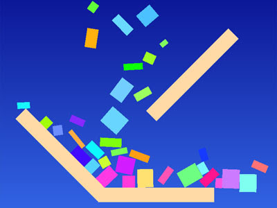
This week, I've gotten 2D boxes working. The environment is made out of (tan) boxes with infinite mass, which makes them immovable. I've got a little chute into which I can drop random boxes:


There's no friction yet. At the moment, gravity is the only force being integrated, so I just integrate assuming constant acceleration during the frame. I may be adding springs or things that require more complex integration, but I'll cross that bridge when I get to it.

In 3D, you have to consider point/face contacts and edge/edge contacts. In 2D, there are only point/edge contacts, so things are a bit simpler. In 3D, the rotational inertial tensor is a matrix, while in 2D it is reduced to a single scalar value.

I'm still struggling to work out a good code architecture. Next up, I plan to generalize my colliding bodies so I can support both boxes and circles; I want to make a simple 2D vehicle, and circles should work for wheels. After that, friction and resting contact.

Everett Kaser's games

Everett Kaser is the master of deductive logic games. From his lair near Corvallis, Oregon he unleashes a steady stream of clever, addictive puzzlers.

If you've ever tried out one of those pen-and-paper puzzles that has three people, three houses, three jobs, and some clues like “The person who lives in the red house is not a carpenter” you know roughly what the games entail. Kaser has designed his games so that the clues are presented in graphical form, and has blended in visual puzzle elements.

For instance, in Honeycomb Hotel you are trying to determine which of several options belongs in each hexagon in the board; but you are also simultaneously trying to determine a Hamiltonian path that enters the board, visits each hex, and exits. Here's an example of a very simple puzzle with two clues:


Each hex contains its possible options; you can eliminate them as you work through the clues. The central hex's contents have been given. The left clue says that the mouse and the letter H are adjacent and connected by a path. The right clue says that the grasshopper and the letter Y are adjacent but separated by a wall.

There cannot be a path connecting the entrance and exit hexes, because then the path wouldn't visit any of the other hexes on the board. This rules out the possibility of mouse and H being on the right side of the board. Once they are placed, Y is known, which places grasshopper and the rest. Here's a partial solution; can you see how to finish it?


Baker Street, another personal favorite, replaces the Hamiltonian path with a tree and is on a board of mixed squares and hexagons, for more varied connectivity:


My wife and I have spent more time on these games than any other. Free demos are available for everything. Give them a try and see if they are to your taste.

Monday, June 11, 2007

2D/3D Vector Classes

Most of my projects end up using vector mathematics, so I've written a couple of classes for handling the 2D and 3D cases. They have evolved a bit over time but have now reached a point where they do most everything I need.

The classes are templatized on the component type, so that I can support vectors of float and vectors of double with the same piece of code. I even use vectors of int sometimes.

There are two different notations for referring to the components of two- and three-dimensional vectors. Sometimes people use the letters x, y, and z since the coordinate system axes are traditionally named the same way. Sometimes people use numeric subscripts instead.

Numeric subscripts are superior to letter subscripts in at least one situation: when you need to choose components programmatically. For instance, let's say you've got a plane in 3D space, and you want to project that plane to 2D (to triangulate a polygon in the plane, say). An easy way to do this is to determine which of the three components of the plane's normal has the largest absolute value, and then use the axes corresponding to the other two components as the 2D projection plane. This type of projection is cheap since it just involves selecting two of the three components of a 3D point; a more general projection would involve dot products against basis vectors, which is computationally more expensive.

Because of the scenario above, I've gone with numeric subscripts in my vector classes. Some vector classes use a union of an array and members named x, y, and z to support both notations; I didn't bother.

Functions that operate on vectors can be standalone, or defined as methods of the vector class. There isn't too much difference either way. I implemented the dot, cross, len, etc. functions as methods of the class because the a.dot(b) notation puts the dot between the operands, like you would do in written math. It also keeps those names out of the global namespace; they are inside the vector class.

The one situation where you can't use methods is when you have an operator that doesn't take a vector as its first argument, for instance if you want to be able to multiply a scalar times a vector with the scalar on the left. This type of function has to be standalone.

The < operator gives vectors an ordering, which allows them to be used as keys in a lookup data structure such as std::map.

The empty constructor allows an uninitialized vector to be constructed, which is nice when you have an if-statement that initializes a vector in one of two different ways.

The +=, *= and similar operators which mutate a vector all return a reference to the vector itself, mimicking the behavior of these operators for standard types such as int. It's not typical or recommended, but you can write a = b += 5;. The vector class supports this behavior in order to be as much like a standard numeric type as possible.

This code is completely standalone, with one exception: square root finding. I use the standard C library functions sqrt and sqrtf for finding square roots of 64- and 32-bit floating point values, respectively. In order to choose the right square-root function for the scalar type at hand, I use template specialization.

These vector classes don't do anything to make use of the SIMD instruction sets that most processors have these days. Using special machine instructions from within C++ is platform-specific, and I have wanted to keep my code simple. Using SIMD badly can result in code that is slower than plain floating-point, too.

Here's the code:

#ifndef VEC_H
#define VEC_H

#include <cmath>

// Square root template, specialized for float or double.

template<typename T> T sqrt_template(T);
template<> inline float sqrt_template<float>(float value)
{
return std::sqrtf(value);
}
template<> inline double sqrt_template<double>(double value)
{
return std::sqrt(value);
}

// A basic 2D vector.
// vec2 = float version
// dvec2 = double version

template<typename T> class vec2_template
{
public:
vec2_template() {}
vec2_template(T x, T y)
{
m_v[0] = x;
m_v[1] = y;
}

bool operator < (const vec2_template & rhs) const
{
if (m_v[0] < rhs.m_v[0]) return true;
if (rhs.m_v[0] < m_v[0]) return false;
return m_v[1] < rhs.m_v[1];
}

bool operator == (const vec2_template & rhs) const
{
return m_v[0] == rhs.m_v[0] && m_v[1] == rhs.m_v[1];
}

bool operator != (const vec2_template & rhs) const
{
return m_v[0] != rhs.m_v[0] || m_v[1] != rhs.m_v[1];
}

T & operator [] (int dim)
{
return m_v[dim];
}

const T & operator [] (int dim) const
{
return m_v[dim];
}

vec2_template operator + (const vec2_template & rhs) const
{
return vec2_template(
m_v[0] + rhs.m_v[0],
m_v[1] + rhs.m_v[1]);
}

vec2_template operator - (const vec2_template & rhs) const
{
return vec2_template(
m_v[0] - rhs.m_v[0],
m_v[1] - rhs.m_v[1]);
}

vec2_template operator / (T f) const
{
return vec2_template(m_v[0] / f, m_v[1] / f);
}

vec2_template & operator += (const vec2_template & rhs)
{
m_v[0] += rhs.m_v[0];
m_v[1] += rhs.m_v[1];
return *this;
}

vec2_template & operator -= (const vec2_template & rhs)
{
m_v[0] -= rhs.m_v[0];
m_v[1] -= rhs.m_v[1];
return *this;
}

vec2_template & operator *= (T f)
{
m_v[0] *= f;
m_v[1] *= f;
return *this;
}

vec2_template & operator /= (T f)
{
m_v[0] /= f;
m_v[1] /= f;
return *this;
}

vec2_template operator - () const
{
return vec2_template(-m_v[0], -m_v[1]);
}

vec2_template operator * (T f) const
{
return vec2_template(m_v[0]*f, m_v[1]*f);
}

T dot(const vec2_template & rhs) const
{
return m_v[0]*rhs.m_v[0] + m_v[1]*rhs.m_v[1];
}

// "Perp dot" product
T perpdot(const vec2_template & rhs) const
{
return m_v[0]*rhs.m_v[1] - m_v[1]*rhs.m_v[0];
}

T sqlen() const
{
return dot(*this);
}

T len() const
{
return sqrt_template<T>(sqlen());
}

vec2_template normalized() const
{
return *this / len();
}

void normalize()
{
*this /= len();
}

private:
T m_v[2];
};

typedef vec2_template<float> vec2;
typedef vec2_template<double> dvec2;

// A basic 3D vector.
// vec3 = float version
// dvec3 = double version

template<typename T> class vec3_template
{
public:
vec3_template() {}
vec3_template(T x, T y, T z)
{
m_v[0] = x;
m_v[1] = y;
m_v[2] = z;
}

bool operator < (const vec3_template & rhs) const
{
if (m_v[0] < rhs.m_v[0]) return true;
if (rhs.m_v[0] < m_v[0]) return false;
if (m_v[1] < rhs.m_v[1]) return true;
if (rhs.m_v[1] < m_v[1]) return false;
return m_v[2] < rhs.m_v[2];
}

bool operator == (const vec3_template & rhs) const
{
return
m_v[0] == rhs.m_v[0] &&
m_v[1] == rhs.m_v[1] &&
m_v[2] == rhs.m_v[2];
}

bool operator != (const vec3_template & rhs) const
{
return
m_v[0] != rhs.m_v[0] ||
m_v[1] != rhs.m_v[1] ||
m_v[2] != rhs.m_v[2];
}

T & operator [] (int dim)
{
return m_v[dim];
}

const T & operator [] (int dim) const
{
return m_v[dim];
}

vec3_template operator + (const vec3_template & rhs) const
{
return vec3_template(
m_v[0] + rhs.m_v[0],
m_v[1] + rhs.m_v[1],
m_v[2] + rhs.m_v[2]);
}

vec3_template operator - (const vec3_template & rhs) const
{
return vec3_template(
m_v[0] - rhs.m_v[0],
m_v[1] - rhs.m_v[1],
m_v[2] - rhs.m_v[2]);
}

vec3_template operator / (T f) const
{
return vec3_template(m_v[0] / f, m_v[1] / f, m_v[2] / f);
}

vec3_template & operator += (const vec3_template & rhs)
{
m_v[0] += rhs.m_v[0];
m_v[1] += rhs.m_v[1];
m_v[2] += rhs.m_v[2];
return *this;
}

vec3_template & operator -= (const vec3_template & rhs)
{
m_v[0] -= rhs.m_v[0];
m_v[1] -= rhs.m_v[1];
m_v[2] -= rhs.m_v[2];
return *this;
}

vec3_template & operator *= (T f)
{
m_v[0] *= f;
m_v[1] *= f;
m_v[2] *= f;
return *this;
}

vec3_template & operator /= (T f)
{
m_v[0] /= f;
m_v[1] /= f;
m_v[2] /= f;
return *this;
}

vec3_template operator - () const
{
return vec3_template(-m_v[0], -m_v[1], -m_v[2]);
}

vec3_template operator * (T f) const
{
return vec3_template(m_v[0]*f, m_v[1]*f, m_v[2]*f);
}

T dot(const vec3_template & rhs) const
{
return
m_v[0]*rhs.m_v[0] +
m_v[1]*rhs.m_v[1] +
m_v[2]*rhs.m_v[2];
}

vec3_template cross(const vec3_template & rhs) const
{
return vec3_template(
m_v[1]*rhs.m_v[2] - m_v[2]*rhs.m_v[1],
m_v[2]*rhs.m_v[0] - m_v[0]*rhs.m_v[2],
m_v[0]*rhs.m_v[1] - m_v[1]*rhs.m_v[0]);
}

T sqlen() const
{
return dot(*this);
}

T len() const
{
return sqrt_template<T>(sqlen());
}

vec3_template normalized() const
{
return *this / len();
}

void normalize()
{
*this /= len();
}

private:
T m_v[3];
};

typedef vec3_template<float> vec3;
typedef vec3_template<double> dvec3;

#endif


At the moment I am taking another crack at learning how to implement rigid body dynamics. This is a fairly well-trod path. I'm working from the highly-influential tutorials by Andrew Witkin and David Baraff. In my case, I'm developing it in 2D, not necessarily because it's any simpler, but because that's what I need it for. I hope to begin writing about it next week.

Bruno Marcos' free Star Wars games

This is rather old news, but Bruno Marcos has written a couple of excellent space shooters using the Star Wars setting. Download them and try them out if you haven't seen them already.


These games are hard; I haven't finished either one. They are intense and addictive, though.

Bruno opted for an airplane-like control scheme. There is a global “up” vector and your X-Wing can't roll or pitch too far away from level with respect to it. This restriction keeps the player's frame of reference much simpler.

Your X-Wing has lasers, which can be configured to fire round-robin, in gangs of two, or all at once. You have a limited number of torpedoes, useful for taking out shield generators on the star destroyers. Your “lives” consist of a finite supply of X-Wings on board one of the battleships. Since you can't resupply once you've launched, sometimes you may want to sacrifice your current X-Wing in order to get a fresh batch of torpedoes. Friendly AI pilots also use the same pool of extra X-Wings, so you want to protect them whenever possible.

The star destroyers launch waves of literally hundreds of TIE fighters which fly in little clusters of four apiece, like in the movies. Once they reach your fleet they break up and circle around, taking shots at battleships and fighters alike. Since the number of defending fighters is so small you have to kill TIE fighters at a furious pace to keep them from destroying your battleships. A big part of the skill in playing the game is figuring out how to shoot them down as efficiently as possible.

The games give excellent feedback. You can get a health reading on any ship by aiming at it. This is useful for deciding which of your battleships need defending the most, or seeing how much more damage you need to do to take out a shield generator. Radio chatter is presented using printed text. There is a counter of how many fighters you've shot down, which serves as your score.

Later on in the Endor battle, the star destroyers move into combat range, and you can get to work taking them down. Star destroyers have multiple targets: the shielf generators, the gun batteries, and the ship itself, and you have to prioritize the targets based on their threat. I usually eliminate the gun batteries that are aimed toward my fleet, then concentrate on taking down the entire star destroyer as quickly as possible, since it continually launches fighter reinforcements.

Note: I haven't had any trouble, but a friend of mine had his machine lock up hard when he tried out these games, so be careful.

Monday, June 4, 2007

Fractal Tiles

Many game textures are designed to tile seamlessly. The left side matches the right and the top side matches the bottom:

Ye Olde Quintessential Brick Texture

What about more interesting ways of tiling? How about a texture that tiles with itself at different sizes on different sides? This could be used to generate a fractal so perhaps it should be called a fractile. Unfortunately it looks like that word's already in use.

I decided to try and make a texture that matches seamlessly with itself on the left and right; with quarter-size copies of itself along the top; and with a quadruple-size copy of itself along the bottom:


(When I'm doing texture mapping I like to use a texture with the letter R on it. It has no symmetries so it immediately tells me which way the surface is oriented.)

In the diagram above the boundary between tiles is a solid color, so they naturally match up seamlessly. Where's the fun in that, though?

This is more like what I had in mind:

Disc diameter and minimum disc spacing are functions of vertical position and vary by a factor of two from top to bottom.

This is how the texture tiles with itself:


I wrote a program to generate this texture. It first places as many discs as it can into the texture; then renders the discs to a bitmap. To place a disc, it picks a random spot, computes the radius based on the Y coordinate, and then checks the existing discs to see if there are any collisions. If not, it adds the new disc to the list. The loop stops after a few thousand tries.

There are a couple of keys to making sure the texture will tile.

  1. When checking for collisions, make sure the proposed disc doesn't collide with any discs in neighboring tiles. These are just translated and possibly scaled copies of the central tile's discs. Note that the bottom edge must match against both the left and the right halves of the top edge, so the existing discs have to be transformed into both configurations.

  2. Any discs crossing the top edge have to be duplicated in the left and right halves of the edge, since both halves have to match against the bottom edge. If a proposed disc's center is near the bottom edge, this will be taken care of by item #1; we check against the discs in the top left and top right. But if a disc overlaps the edge and has its center near the top, we need to generate a doppelgänger disc offset by half the texture width and test it for collisions as well. If there are no collisions, add both the disc and its doppelgänger to the list. You can see two discs that have doppelgängers in the example texture above.


To make a more interesting texture, I used the disc centers to generate a Voronoi diagram. Voronoi diagrams give a nice, cobblestony look, and everything connects together so the texture appears to be harder to create.


Obviously I've used much smaller discs in this case. Like everything else, the line width between Voronoi cells scales up by a factor of two from top to bottom. Here's how it tiles with itself:


The Voronoi-based texture was slightly trickier to produce. In particular, it's no longer sufficient to ensure that only discs crossing the top edge have doppelgängers, because there may be discs that don't cross whose Voronoi regions nevertheless do cross the edge. What we really need to ensure is that all the Voronoi edges crossing the top edge are identical in the left and right halves. To get around this, I used a bit of a hack: I generate disc doppelgängers whenever the disc center is in the upper quarter of the texture. This is overly conservative; you can see duplicate Voronoi regions that don't cross the top edge. It was very simple to implement, though, and the results don't look bad.

Here's the texture placed on a large disc:


The disc is built out of concentric rings. Each ring has twice as many copies of the texture as its inner neighbor:


I've purposely not shown the center of the disc. Things get screwy there. Ideally I'd probably want to co-generate another texture that was designed to fit into the center of the disc and match up with the other textures surrounding it.

The impetus for this is that I've been trying to figure out how to model and texture a 2D representation of a planet. Think of Lunar Lander and Moon Patrol combined together and placed on a disc instead of a flat world. Most of the action takes place on or above the surface of the planet, so you don't ever see the center of the disc unless you are zoomed out (as in the pictures above), and you need very fine detail at the surface.

It's been amusing to work this out. Now that I've seen it, I'll probably go in another direction, but who knows? You might find it useful or at least entertaining.

Have fun, and see you next week!